Thursday, December 8, 2016

1310nm, 1550nm, Expansion and Monitor Ports on CWDM MUX/DEMUX

CWDM technologies have been widely accepted low cost and fast solutions to increase capacity of the existing fiber optic network without adding new fibers. To add more beneficial to CWDM networks, CWDM MUX/DEMUX, which is used to multiplexing and demultiplexing optical signals, is being added with special ports like expansion port, monitor port, 1310nm port and 1550nm port. What’s the function of these special port? Do you really need them on your CWDM MUX/DEMUX? This post will offer details about these special ports for your references.
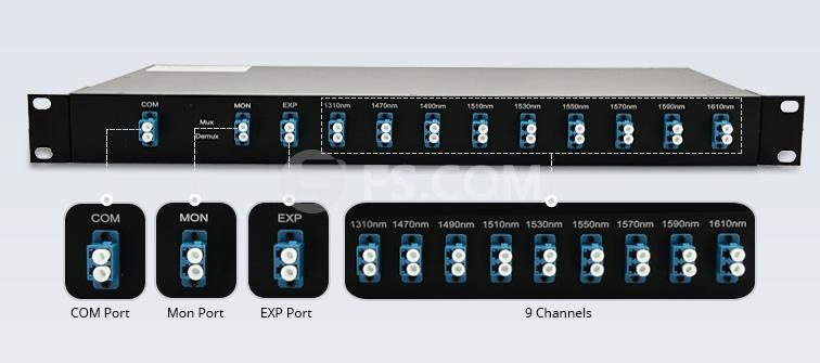
1310nm, monitor port and expansion port
Special 1310nm Port and 1550nm Port on CWDM MUX/DEMUX
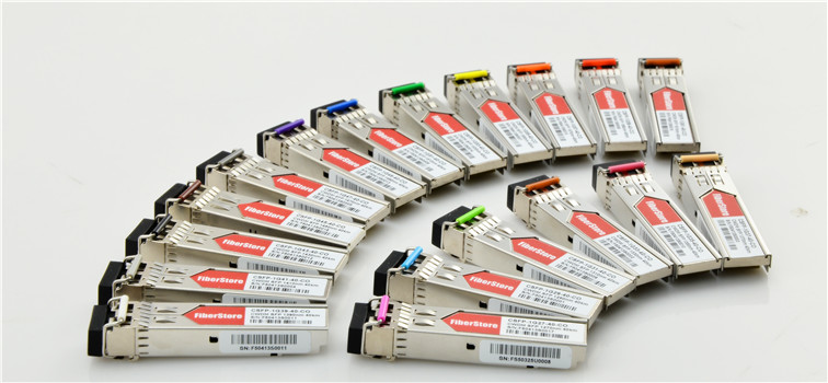
CWDM utilizes usually wavelength range from 1270nm to 1610nm with a channel space of 20nm, which means the 1310nm and 1550nm are also the CWDM wavelengths. A full channel CWDM MUX/DEMUX can have 18 channels using 1310nm and 1550nm as channel ports. Actually, in most cases, 1310nm and 1550nm are used as channel port in CWDM MUX/DEMUX. They should be connected to the corresponding colored CWDM fiber optic transceiver, like CWDM 1310nm SFP and CWDM 1550nm SFP+.
As 1310nm and 1550nm are usually used for long distance transmission in normal fiber optic network. Most long distance fiber optic transceivers are designed to work over 1310nm and 1550nm. For example, 10G SFP+ LR transceiver is working over 1310nm and 10G SFP+ ZR is working over 1550nm. The Special 1310nm port and 1550nm port on CWDM MUX/DEMUX can be directly connected to these transceivers to expand the capacity of CWDM network. This is the main function of the 1310nm and 1550nm ports on CWDM MUX/DEMUX.
CWDM SFP
However, the special 1310nm and 155nm ports can affect the transmission of the wavelengths near it. The two port cannot be added freely. If you want to add 1310nm or 1550nm ports on your CWDM MUX/DEMUX, wavelengths which are 0-40 nm higher or lower than 1310 nm or 1550 nm cannot be added to the MUX. The following shows the ports that you can add on your CWDM MUX/DEMUX in different cases.
  • If you add 1310nm port, the following ports can be added: 1370nm, 1390nm, 1410nm, 1430nm, 1450nm, 1470nm, 1490nm, 1510nm, 1530nm, 1550nm, 1570nm, 1590nm, 1610nm
  • If you add 1550nm port, the following ports can be added: 1270nm, 1290nm, 1310nm, 1330nn, 1350nm, 1370nm, 1390nm, 1410nm, 1450nm, 1470nm, 1490nm
  • If you add both 1310nm port and 1550 port, the following ports can be added: 1270nm, 1290nm, 1310nm, 1350nm, 1510nm, 1530nm, 1550nm, 1570nm, 1590nm
Expansion Port on CWDM MUX/DEMUX
Although CWDM has 18 channels that can be used for transmission, in many cases, not all these channels are needed at one time or when the CWDM network deployed. But once you want to add more wavelengths to the existing CWDM network, the expansion port on CWDM MUX/DEMUX will play an important role, which can combine two individual CWDM MUX/DEMUXs with different wavelengths as one CWDM MUX/DEMUX.
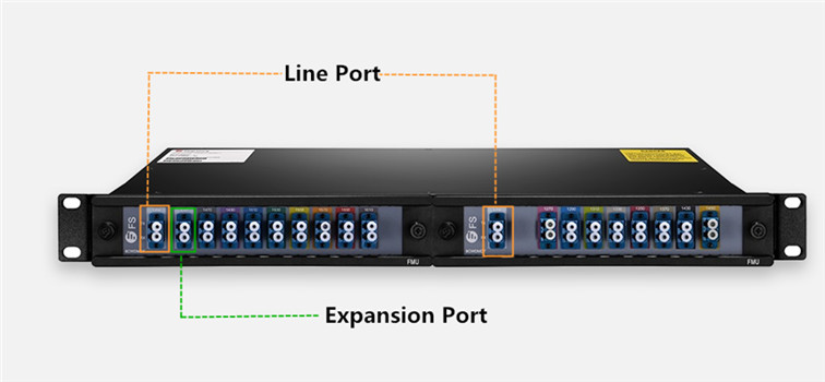
CWDM MUX/DEMUX with expansion port
Here takes this 16-channel FS.COM FMU CWDM MUX/DEMUX as an example. There are two half-U plug-in CWDM MUX/DEMUXs deployed in a 1U rack. The module on the left side has an additional expansion ports. If you connect the expansion port with the line port on CWDM MUX/DEMUX on the right side. The two CWDM MUX/DEMUXs can work as one. This is the magic of the expansion port. If your network hasn’t used all the CWDM channel and you can to add more in the future, you can buy add an expansion port on your MUX/DEMUX or add the expansion port on the new CWDM MUX/DEMUX in the future.
Monitor Port on the CWDM MUX/DEMUX
Unlike the above mentioned three special ports which can increase the capacity of the CWDM network, the monitor port literally is used for monitoring the CWDM network. In many cases, the monitor port is necessary which can simplify turn-up operations of CWDM networks, and can be used for in-service monitoring of the CWDM signals by connecting an optical spectrum analyzer or a power meter.
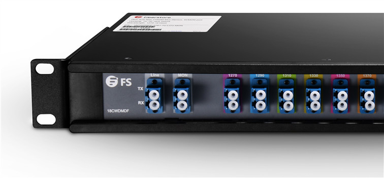
4-channel CWDM with monitor port
Conclusion
The 1310nm port, 1550nm port and expansion port are designed to increase the capacity of CWDM network. The Monitoring port is added for better network management and operation. Except the 1550nm port, all these port can also be added on the DWDM Mux/DEMUX and play the same function. Kindly visit WDM page for full series of CWDM and DWDM solutions, if you are interested.
Sunday, July 31, 2016

Which Fiber Patch Enclosure Fits Your Data Center Application?

Fiber patch enclosure, providing solid fiber optic links protection and easy & fast cable management, is becoming a must-have component in data center and server room fiber cabling. As data center cabling requirements are various, fiber patch enclosures also have a lot of designs. Selecting the right fiber patch enclosures can largely increase the working efficiency and decrease the costs for labor and time. Which fiber patch enclosure knows fits your data center requirements best? Here will introduce several most commonly used and affordable fiber patch enclosures that are used for data center cabling.
Fiber Patch Enclosure Divided Overall Design
There are two widely used designs of fiber patch enclosures in general: wall mount fiber patch enclosure and rack mount fiber patch enclosure. The functions of the two types fiber patch enclosures can be literally understood. Usually, a wall mount enclosure can be installed directly on wall for fiber cabling. A rack mount fiber patch enclosure usually has a industry standard 19 inch wide rack unit (RU) design and can be installed on a rack for fiber cabling. For higher fiber count, the rack mount fiber enclosure could be 2/4/6/12RU or more.
fiber enclosure
The rack mount fiber patch enclosure also has two versions in general. One is a fixed one with a lid which can be removed from the enclosure for fiber cabling, the other one is a slide-out fiber patch enclosure. Currently, the most popular rack mount fiber patch enclosure is usually has a slide-out design, which allows customers to remove the whole enclosure from the rack and provides easier internal fiber connection access.
rack mount fiber enclosure
Fiber Patch Enclosures With Different Front Panel
The front panel of a fiber patch enclosure is also very important which can directly affects the fiber count that an enclosure can provide and the cabling methods. To fit various fiber cabling environments and network applications, the fiber patch enclosure front panels come in a variety of types. Here will introduces several most popular fiber enclosures with different front panel designs.
fiber enclosure front panel

Fiber Patch Enclosure With Fixed Front Adapter Panel
A fixed front adapter panel is usually a 19 inch wide fiber adapter panel which can be installed on the fiber patch enclosure to accommodate various fiber optic connectors. The port number and fiber adapter type will determine the fiber count and connector types that can be installed with the fiber patch enclosures. The following picture shows a 1U fiber adapter panel loaded with 24 duplex LC adapters which can provide up to 48 fiber optic connections. This fiber adapter panel can be installed on fiber patch enclosure working as the front panel.
12-duplex LC fiber adapter panel

Fiber Patch Enclosure With Removable Adapter Panels
Driven by the requirement for higher cabling density and flexible cabling methods, the front panel of a fiber patch enclosure could be composed by several individual fiber adapter panels which could be loaded with the same or different types of fiber optic adapters. Meanwhile, these individual fiber adapter panels can provide various types of adapters and higher cabling density. Generally, up to three 12 duplex LC port fiber adapter panels with industry standards can be installed on a 1U rack mount fiber enclosure. However, a smaller version of fiber adapter panel is also provided. Up to four 12 duplex port fiber adapter panels can be installed on a 1U rack mount fiber enclosure.
fiber optic adapter

Fiber Patch Enclosure With Removable MTP/MPO Cassettes
The fiber adapter panel that installed on the fiber enclosures required additional internal fiber cabling, which usually uses fiber pigtails. As 40G/100G fiber networks which use MTP/MPO interfaces are gradually being deployed in today’s data center, the cabling methods become more complex. To simplify the cabling methods, MTP/MPO cassettes are being introduced to the market. Up to three LGX MTP/MPO cassettes can be installed on a 1U fiber panel enclosure. With these cassettes, the internal cabling of a fiber patch enclosure could be eliminated. For higher cabling density, there is also a high density cassette. Up to four of the HD MTP/MPO cassettes can be installed on a 1U fiber panel.
MTP/MPO cassette
Conclusion
The above mentioned fiber patch enclosures are the most commonly used ones in today’s applications. The cabling environments of every data center are different. Finding the right fiber patch enclosures means a lot. Excepted standard fiber enclosures, there are also a lot of customized fiber enclosures that are provided in FS.COM. Customer can design their own fiber patch enclosures in FS.COM according to their own applications.

Wednesday, July 20, 2016

How to Build 10G CWDM Network

As a passive technology, CWDM allows for any protocol to be transported over fiber optic link at specific wavelengths. CWDM technology is a cost-effective and simple method to increase the capacities of fiber optic network, by using different wavelengths to carry different signals over a single optical fiber. The wide deployment of CWDM network is greatly driven by its affordable cost.

What Is Need for A 10G CWDM Network?

The deployment of a 10G CWDM network is relaying on the exiting fiber optic network. Adding some components on the existing network can largely increase its capacity for data transmission. Here will introduce the key component and an important step during 10G CWDM network deployment.
CWDM Mux/Demux
A Key Component—CWDM Mux/Demux
A key component should be deployed is CWDM Mux/Demux, which combines different wavelength signals from different optical fibers into a single optical fiber, or separates different wavelength signals coming from a single optical fiber to separate optical fibers. The Channel number of a CWDM Mux/Demux is an important factor to divide this device. Standards have identified 18 CWDM Channels. Most of the CWDM Mux/Demux are provided with Channel number range from 2 to 16. However, FS.COM provides a 18-Channel CWDM Mux/Demux which can increase capacity of CWDM network to the most. CWDM Mux/Demuxs also come into a variety of package form factors. The most commonly used are LGX design, rack design and pigtail design.
CWDM Cabling

An Important Step—Connecting CWDM Mux/Demux With 10G Switch
Connecting CWDM Mux/Demux with a 10G switch, is the most important step to build a 10G CWDM network. In simple, to add more devices on the fiber optic network by CWDM technology is to connect the CWDM Mux/Demux with the 10G switches which are linked to the end users. To link CWDM Mux/Demux with the switches, fiber patch cable and 10G CWDM SFP+ transceiver are needed. 10G CWDM SFP+ transceiver should be installed on the switch SFP+ port (some switches use XFP port, then 10G CWDM XFP transceiver is required). Then a length of fiber patch cable should be used to link the transceiver and CWDM Mux/Demux.
CWDM SFP+
How to Select to Right 10G CWDM SFP+ Transceivers?

Choose the Right Working Wavelength: To ensure the right connection, the specific wavelength port should be connected to the same wavelength CWDM SFP+ transceivers. For example, the port on the CWDM Mux/Demux marked with 1270 nm, should be connected to a CWDM SFP+ transceiver that working over wavelength of 1270 nm. As there are 18 different CWDM wavelengths, 10G CWDM SFP+ transceivers that are provided in the market also can 18 different versions for these wavelengths.
Choose the Compatible CWDM SFP+: It is common sense that the fiber optic transceiver should be compatible with the switch which it works on. For instance, if you are using a Cisco switch, the fiber optic transceivers that you used with this switch should be original Cisco transceivers or Cisco compatible transceivers which are provided by third party vendors. The latter is usually the choice of many companies, this is because third party transceivers are usually more cheap than the original brand transceivers. Fiber optic transceivers provided by third party vendor like FS.COM are all fully tested on original brand switch to ensure their compatibility and quality. What’s more, most of FS.COM fiber optic transceivers support same day shipping. Select the right SFP do not only cut your cost and time, but also provide high network performance.
Choose the Transmission Distance According to Your Needs: CWDM network is usually deployed for long distance transmission. Thus the 10G CWDM SFP+ transceiver that are provided in the market usually support transmission distance longer than 20 km, some can support link length up to 80 km or more. You can select the 10G CWDM SFP+ according to your requirements.
Here list the generic whole band 10G CWDM SFP+ fiber optic transceivers that support link length of 20km, 40km and 60km. If you need the brand compatible CWDM SFP+, kindly contact sales@fs.com or visit FS.COM for more details.

Wavelength 20km CWDM SFP+ 40km CWDM SFP+ 60km CWDM SFP+
1270 nm 44170 44363 44743
1290 nm 44171 44364 44744
1310 nm 44172 44365 44745
1330 nm 44173 44366 44746
1350 nm 44269 44367 44747
1370 nm 44270 44368 44748
1390 nm 44271 44369 44749
1410 nm 44272 44370 44750
1430 nm 44273 44371 44751
1450 nm 44274 44372 44752
1470 nm 44299 44550 44827
1490 nm 44300 44551 44828
1510 nm 44301 44552 44829
1530 nm 44302 44553 44830
1550 nm 44303 44554 44831
1570 nm 44304 44555 44832
1590 nm 44305 44556 44833
1610 nm 44306 44557 44834
Conclusion
With the improvement of technology and market, the cost of CWDM network has decrease a lot. To build a 10G CWDM network is affordable to most companies. For full series of CWDM network Solutions, please visit the following link: WDM Solution

Thursday, July 14, 2016

Fiber Patch Panels for Ultra High Density Cabling

How to build a flexible and manageable cabling system in high density cabling environment is becoming an issue which has attracted increasing attention of many data centers. Cable management components like fiber patch panels have kept upgrading to meet the increasing needs for high density cabling. Proper using of fiber patch panels does not only provide well management for fiber patch cables in data center, but also protects the fiber patch cables and reduces the risks of faults cause by problems like bend loss, dusts and wrong connections. For ultra high density cabling like 40G and 100G connections, things would be more complex. Luckily, with clever design of fiber patch panels, customers won’t worry about fiber cable mess and faults caused by bad cable management.
ultra high density cabling
Larger Fiber Count Means More Space Requirements
For 40G network, the backbone core signals are generally distributed into 4 strands of 10G signals in first. This process usually employs fanout MTP to LC fiber patch cables. For example, a 8-fiber MTP to 4 LC duplex fiber harness cable provides 8 fibers for 4 ways of duplex transmission. It means a fanout cable with a MTP connector and 8 legs terminated with LC connector added in data center for a single duplex way of 40G transmission. In data center, a lot of 40G network should be built, which means the fiber cable count will be largely increased. Not to mention the 100G applications, which will increase at least 10 fibers for every 100G signal distribution.
Using Modular Design to Reduce the Space Requirements
To solve this problem, a series of fiber patch panels have been invented for 40G and 100G signal distribution applications. Here introduce two versions of ultra high density fiber patch panels which are designed for 40G and 100G applications separately: 1U 96-fiber MTP to LC breakout fiber patch panel and 2U 160-fiber MTP to LC breakout fiber patch panel. Both of them use the industry standard rack unit design, which can be installed on any standard rack.
96-fiber MTP to LC breakout fiber patch panel
1U 96-Fibers MTP-LC Fiber Patch Panel for 40G Applications
The above picture shows the details of this 96-fiber breakout patch panel. On the back panel of this unit, there are 12 8-fiber MTP adapters which are separately linked 12 groups of LC duplex adapters on the front panel. Each of the 12 groups has 4 duplex LC adapters which can support 4 ways of 10G duplex transmission. Thus, the whole fiber patch panel can support up to 12*40G transmission in duplex ways. To decrease the error connections, each port has been clearly identified by numbers and groups.
160-fiber MTP to LC breakout fiber patch panel 160-Fiber MTP-LC Fiber Patch Panel for 100G Applications
A 160 fibers MTP to LC fiber patch panel uses a standard 2U rack design, which uses the same theory of the above mentions 96-fiber 40G fiber patch panel. The distribution of the 100G signals is generally achieved in 10*10G. There are 8 20-fiber MTP adapters on the back panel of this 100G fiber patch panel. Each of them connects a 20-fiber MTP adapter on the back panel to a group of 10 duplex LC adapters on the front panel. Thus, 8*100G duplex transmissions can be achieved with this 2U rack.
Conclusion
The above mentioned 1U 96-fibers MTP-LC fiber patch panel for 40G and 160-fiber MTP-LC fiber patch panel for 100G applications do not only decrease the space requirement for ultra high density cabling environment, but also decrease the faults caused by cable clutter, connection, disconnecting or bend loss by protecting the optical fiber in side a strong and reliable box. Kindly visit FS.COM or contact sales@fs.com for more details about ultra high density patch panels, if you are interested.

Friday, July 1, 2016

How Many Choices Do You Still Have for Fiber Patch Cable?

Fiber patch cable, also known as fiber jumper, is a key component in today’s fiber optic network. They play the role of veins in the whole fiber optic network bringing fiber optic signals between devices.
How to Select Standard Fiber Patch Cable?
During the selection of standard fiber patch cables, several questions are usually take into consideration:
  • What’s the fiber type of the patch cable? The available selection are Multimode (OM1, OM2, OM3, OM4) and single-mode (OS1 and OS2).
  • What’s the connector type and connector polishing type on the two ends of fiber patch cable? Currently the most commonly used fiber patch cables are usually terminated with LC, SC and MPO connectors.
  • What’s the fiber count of the patch cable? Simplex (one fiber) and duplex (2 fibers) fiber patch cable are very common. For fiber patch cables terminated with MTP/MPO connector or breakout fiber patch cables. Their fiber count would be larger, sometime up to 24 fibers or more.
  • What’s the material of the fiber patch cable jacket? PVC, LSZH, Armored, and OFNP are the choice of most situations.
Not All Fiber Patch Cable Are Created Equal
Now with the fiber optic cable being widely used in a variety of industries and places, the requests for fiber patch are being refined. Fiber patch cable are being required to be improved and provide more possibilities to satisfy various application environments. Actually, many specially fiber patch cable have been created to answer the market call. Here will introduce several unique but useful fiber patch cable for your references.
Bend Insensitive Fiber Patch Cable for Lower Signal Loss
Bend loss issues are always a headache problem for most fiber optic network designers and installers. Why? Cause signal loss caused by bend loss issues are really hard to handle. In addition the bend loss issues are difficult to locate. That’s why bend insensitive fiber patch cables are created. Literally, it tells us that this type of fiber patch cable is not as sensitive as other fiber patch cables. The secrets is lays on the fibers which is made of bend insensitive glass. More and more data centers and FTTH systems are tend to use these bend insensitive fiber patch cables, because they do not provide lower signal loss, but also provide a much more durable and easy to maintain networking environment. Fiber optic installer is able to save installation cost with faster installation due to easier fiber optic cable handling.
bend insensitive fiber patch cable
Keyed LC Fiber Patch Cable for Data Security
Keyed LC fiber patch cable, is also called secured LC fiber patch cable. This is because, the fiber optic connectors on the two end of the patch cable are specially designed LC connectors, which can ensure the data security at the mechanic level. Keyed LC fiber patch cable is identifies by the connector color. Keyed LC fiber patch cable is just a part of the Keyed LC connectivity product family. It should be used with the same colored fiber adapters or fiber adapter panels. Each color of a set of keyed LC connectivity products represents a unique keying pattern that only allows matched color mating. This is how keyed LC fiber patch cable can provide data security for fiber optic network. A previous article (Secure Fiber Optic Link With Keyed LC Connectivity Products) of my has introduce keyed LC connectivity in details, kindly follow the link on the article title if you need more information about them.
keyed-lc-connector-and-adapter
Uniboot LC Fiber Patch Cable for Easier Cable Management
Uniboot LC fiber patch cable is a fiber patch cable with two fibers wrapped in the same strand of cable. A duplex LC fiber optic connector which can provide easy polarity reversal is terminated on each end of the uniboot LC fiber patch cable. The following picture show the polarity reversal of a typical uniboot LC fiber patch cable. With less cabling space are require, better cooling is available. With easier polarity reversal, no additional tools are required. And easier cable management can be enjoyed.
uniboot LC fiber patch cable
HD TAB Fiber Patch Cable for Space Saving
HD (high density) TAB fiber patch cable is a fiber patch cable with its connectors attached with a push pull tab, which can provide easier finger access and cable locating. Today’s fiber optic network is increasing depended on high density which results in difficult finger access and difficult cable management. With a push-pull tab attached on the connector, problem are solved easily. The connecting and disconnection of fiber patch cables will be easier without affecting other surrounding links. Currently most HD TAB fiber patch cables available the market are terminated with LC and MTP/MPO connectors. For more information about this type of patch cable kindly visit my article: Cabling With High Density Push-Pull Tab Patch Cords.
HD TAB fiber patch cable
HD Uniboot LC Fiber Patch Cable—Space Saving to the Extreme
HD uniboot LC fiber patch cable combine the advantages of uniboot LC fiber patch cable and HD TAB fiber patch cable. Combining two optical fibers in a single cable strand and attaching a push-pull tab on the connectors, HD uniboot LC fiber patch cable can minimize the required cabling spaces to extreme. It is an ideal solution for high density cabling environment.push-pull tab patch cords connectors
Except the standard fiber patch cable, there are still a lot of choices which can meet the requirements of various networking environment. All the above mentioned fiber patch cable are all available in FS.COM. Kindly visit FS.COM or contact sales@fs.com for more details.

Friday, June 24, 2016

Cable Tie Is Not as Easy as You Think

When think of cable ties, most people would firstly thought of a bunch of self-locking throwaway plastic strips. One might think a cable tie is just a cable tie. There are many uses for cable ties. And there are also a wide variety of cable ties which are designed for different applications. The plastic self-locking cable ties are the most commonly used ones. However, even these simple plastic loops come into various types according to their color, length, width, and serrations. Proper cable ties do not only provide long-life and dependable services but also better cable management, especially in data centers and server rooms which are the worlds of various cables. To choose the right cable tie for your applications, this post would like to offer some suggestions when making your decisions.
cable tie
Locking Design of Cable Tie
Self Locking Cable Tie: The most important thing of a cable tie is its locking technology. With a good locking design, cable tie can provide firm locking for the cables. The most commonly used cable tie is also called zip tie, which is one-piece design with a lot of serration on the cable tie to lock the cables firmly. The following picture shows the structure of this cable tie. This design allows the cable tie to perform to the published minimum tensile strength.
self locking cable tie
Reusable Self-Locking Cable Tie: The zip tie is easy to use and affordable. However, this type of cable tie cannot be reused, cause once the cable tie is locked it would be really hard to unlock or release it. You have to cut them down if you don’t need them. To improve this design, a little latch is added on the tongue of the cable tie, which makes the cable ties reusable. As shown in the following picture, the reusable self-locking cable tie can be easily released by pressing the latch on the tongue, which can perfectly ignore the affection of the serrations on the cable tie.
reusable cable tie
Magic Velcro Cable Tie: This type of cable tie is also reusable. The hooks and hairs on the cable tie can provide firm locking for the cables (shown in the following pictures). And it can make cable management safer and more convenient. It is also widely used in household applications to organize wires. This Velcro cable tie is usually sold in rolls.
velcro cable tie
Identification Cable Tie: the above mention cable ties are all available in different colors. Color is a useful feature for identification. Thus, customers can use cable tie in different colors for identification. However, it happens that the color is not enough for cable identification if there are too many cables or too much information. Then, an improved cable tie with a marker or label attached on the cable tie is offered (shown in the following picture).
identification cable tie
Materials of Cable Tie
The function and performance are also largely depended on the materials of the cable ties. The above mentioned cable type are the most commonly used ones, which are usually made of plastic, Nylon and Velcro. However, for some harsh environment, elements like temperature and strength should be considered during cable tie selection. There is a type of cable tie which is made of stainless steel, usually known as heavy duty stainless steel cable tie(as shown in the following picture). It is commonly used in outdoor applications.stainless steel cable tie
Other Factors to Consider During Cable Tie Selection
The length of cable ties available in market ranges from 4 to 52 inches. The cable tie length should be longer than the diameter of the cable bundle. It cannot be too long or too short. The proper width of a cable tie will also help a lot. Both the length and width of the cable ties should be depended on the applications.
Cable Ties Solutions
The above mention cable ties are all listed in the following table for your reference. You can Click HERE or contact sales@fs.com for more details about cable tie.
Products Description
Nylon cable ties available size: 2.5*12mm, 3.6*150mm, 4.5*120mm, 5.5*200mm; available in various colors
Velco cable tie available size:50*100mm, 10*100mm, 30*100mm, 100*100mm, 15*100mm; available in various color
Identification cable tie available size: 1*5/16Inch, 11/8*5/8Inch, 11/8*5/8Inch; available in various color
Reusable cable ties available size: 8*0.19Inch, 8*0.19Inch, 10*0.19Inch, 12*0.19Inch; available in various color
Stainless steel cable tie available size: 8Inch, 10Inch, 12Inch

Thursday, June 9, 2016

Which Fiber Media Converter Is Perfect for Your Project?

Fiber media converter is a simple but useful devices that can provide conversion between fiber optic and other types of media. The most common use of fiber media converter is transmission between fiber and copper to extend the network or introduce fiber optic cabling to a copper based network. As these devices can be installed almost everywhere in the network and it is affordable, they are also being designated for many other applications. Various types of fiber media converters are provided in the market, people easily get confused during selecting the best ones for their projects. In this post, the fiber media converter selecting guide will be offered for your references.
fiber media converter
Factors to Consider During Fiber Media Converters
To select the right fiber media converters for your project, many elements should be considered. You should firstly consider where you want to use fiber media converters and how to use them. Then, You should know the functions and characters of fiber media converters. The following will list some important factors that should be considered during fiber media converters selection.
Data Rate: the speed of the devices that fiber media converter is to connect to should be firstly considered. The most commonly used are 10/100Mpbs, 10/100/1000Mpbs, 1000Mpbs.
Fiber Type: which two different types of transmission medias should be converted between each other? For example, fiber optic to copper, single-mode fiber optic to multimode fiber optic, dual strand or single strand, etc.
Wavelength: to add the fiber media converters to a fiber optic network, the wavelength that the signal should be specified to the network and the devices.
Port Type and Port Number: fiber media converter also have various port type. The most commonly used types for fiber optic on the fiber media converters are ST, SC and SFP. The number of the power should depend on the applications.
Transmission Distance: the transmission distances of a pair of fiber media converter are also various and can satisfy various requirements from 2km to 15km or more.
PoE Function: PoE fiber media converter can fully satisfy the need to be powered in physical locations where main power is not available or difficult to deliver.
Power Requirement: the most commonly used are AC power supply, DC power supply,, internal power supply, and external power supply.
Fiber Media Converters According to Applications
The above mentioned are the basic factors that should be considered during selection. However, as mentioned the applications are also very important. To offer a more simple and direct way for fiber media selection. Here collected the different fiber media converters and divided them according to their applications. Click the fiber media type in the following table, you can find the fiber media converters belong to this catalog, with their specifications and prices in details.
ethernet-1Fiber to RJ45 Converters sfp-rj45SFP Ethernet Converters
oeoOEO Converters modeMode Converters
management-converterManaged Ethernet Converters poePower over Ethernet Products
video-1Fiber Video Converters pdhPDH E1 & Serial Converters